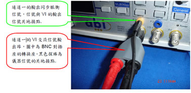
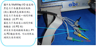
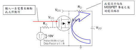
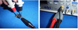
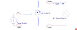
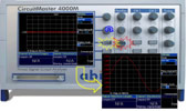
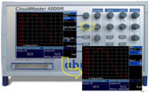
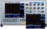
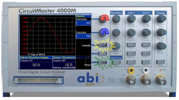
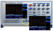
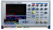
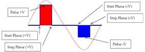
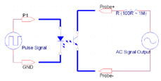
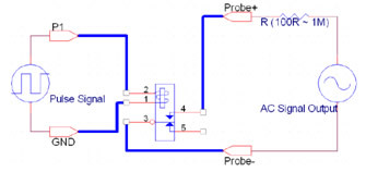
In the test methods of MOSFETs, optocoupler components and relays, it is mainly based on whether the operating state can be correct to determine whether the component is working properly. In the VI curve test function of ABI4000M, you can test the function of these three components. Next, we will first explain the basic structure of these three components, then explain how the ABI4000M tests these three components, and finally explain how to operate the ABI 4000M to test the above three components. Partial test connection instructions of ABI 4000M: A. Description of the basic components and test methods of field-effect components (MOSFET), optical coupling components and relays: 1. Basic test circuit for field-effect components (MOSFET): Here we only use simple IRF950 (P channel) components for illustration. 2. Test method of MOSFET with VI curve function of ABI4000M: When using the Circuit Master 4000M for testing, you can connect the MOSTFET to the instrument according to the above diagram. Probe +: the red probe in the picture. Probe-: the black probe in the picture. (Because GND and Probe- are the same point, just choose one to connect) 3. Operation mode of ABI4000M: The connection method with the component can be connected according to the previous step. The following uses color differences to illustrate the operation method: STEP1: Red: Turn this knob to set the "VI Curve" VI curve function. Blue: This software is used to set the tested channel to Ch1 or Ch2. Yellow: After the above settings are completed, press this key to enter the set measurement function STEP2-Red: press this knob to enter the Setup function screen (as shown below), blue: you can use this knob to select the output of the synchronization signal (P1, P2 or P1 + P2). Yellow: use this software to select the display Mode (VI or VT), but currently must be selected in VT mode Step3-Yellow: You can press this knob to set the output amplitude of the sync pulse. After pressing, the setting screen as shown in the figure below will appear (the sine wave mode currently shown below is the wave mode that has not been connected to any components) STEP4-Red press this knob to enter the P1 synchronization pulse signal intelligence and setting vector screen, yellow: press this button to enter the P2 synchronization pulse signal intelligence and setting vector screen. Step5-Yellow: Press this key to set the output of negative sync pulse. (If you select Enable for output). Because it is currently on the setting page of Negpulse (negative pulse), only the parameters of the negative pulse can be selected. To select the setting of the positive pulse, you must press the red step button in the previous step to enter the Pospulse (positive pulse) setting page. Red and blue: These two knobs can be used to adjust the start phase and stop phase of the sync pulse. Green: You can use this software to return to the previous setting page. Step6-At this stage, you can connect the tested component, you can return to the first page to refer to the connection method provided. Red and blue: The two knobs can be adjusted on this setting page, and the output amplitude of the sync pulse can be adjusted arbitrarily, and the measured waveform will be reflected on the screen in real time. Step7-So far, we can see the waveform shown in the figure below, but when testing different components, the matching impedance of voltage, frequency and output are all more critical adjustment parameters. The tester can set each parameter value to be tested according to the adjustment method below. VI signal voltage amplitude setting (10Vpp): It can be adjusted by the knob shown in red in the figure above. (From 1Vpp to 50Vpp) VI signal output frequency setting (1KHz): It can be adjusted by the knob shown in blue in the figure above. (From 10Hz to 10KHz) VI signal output negative cut setting (1K): It can be adjusted by the knob shown in yellow in the figure above. (From 100R to 1M) VI signal waveform setting (sin): You can use the knob shown in green above to click to switch the currently set VI signal type. (Sine wave-> triangle wave-> square wave-> ramp wave-> reverse ramp wave-> forward pulse wave-> reverse pulse wave) Special Note: Here are the following diagrams for the set parameters: The two parameter settings in the previous step, one is "Pulse + V" and "Pulse –V", and the other is "Start Phase" and "Stop Phase" In the above schematic diagram, the red part is the forward pulse signal, you can set the forward voltage amplitude and the start and end duty cycle settings. Blue is the negative pulse signal, the same parameters can be set. B. Optocoupler: (Photo-optocoupler) The connection method of the optocoupler is shown in the figure below, and the setting method is the same as the setting method of the MOSFET. C. Relay: (Relay) The measurement connection method of the relay is shown in the figure below, and the setting method is the same as the setting method of the MOSFET. However, one should pay attention to the setting of Pulse voltage, that is, the Pulse voltage can only be output to +/- 10V, so for relays that can be driven more than 10V, you must use an external power supply (this part will Added in the future). Silicone Baking Mat,Cookie Baking Mat,Silicone Baking Pastry Mat,Grill Cooking Mat Changshu Xinneng Silicone Products Co., Ltd. , https://www.xnmat.com