At present, there are many kinds of control strips used at home and abroad. The Bruner control strip is recommended for China's national printing standard. As a quality control tool used by the national printing industry, GATF number signal strips, FOGRA measurement strips, etc. are commonly used in the country. Regardless of which control strip is selected, they all have common measurement elements that help monitor the production process. The following is a brief introduction of Bruner's control bar function and application method.
Stainless Steel Bottles are made from high-grade 18/8 stainless steel. This material is food grade, non-toxic, durable and easy to clean.
And we got a lot of different kinds of Stainless Steel Bottles. For example: Stainless Steel Cola Bottle, a classic design that is popular in the market and easy to use, also looks good. Speaking of looking, our Cola Bottle comes in changeable colors and diverse patterns.
1. Structure composition
The Bruner control strips are used for the measurement and calculation of field density, dot gain, dot distortion, and print contrast (K value) for proofing and printing, both for density metering and for visual inspection. There have been several versions of it, but most currently use the latest version with seven control segments, as shown in Figure 1. 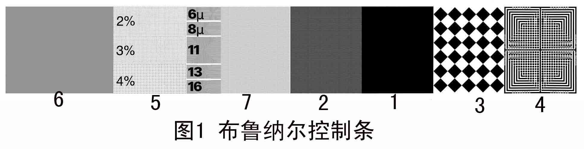
Figure 1-1 shows a solid patch segment. Figure 1-2 shows a 75% thin segment. Figure 1-3 shows a 50% coarse mesh (10 lines/cm) segment, as shown in Figure 1-4. It is a 50% thin network micro-measurement segment. Figure 1-5 shows the fine line and small dot control segment. Figure 1-6 shows the gray balance observation segment. Figure 1-7 shows the 25% fine segment.
2. Function and usage
(1) Solid patch segments, as shown in Figure 2-1.
Functions: 1 Measure the proofing, the density of printing on the spot and the degree of ink inking; 2 Measure and calculate the three major characteristics of the three primary colors ink, namely color shift, ash and efficiency.
When measuring with a densitometer, Bruner recommends using a narrow-band, non-polarized densitometer (with a measurement aperture of at least 3.5 mm).
The best field density value for controlling four-color inks is not only the core of color proofing for proofing and printing data, but also the core of data color management in the entire copying process. Because the density of the ground (ink layer thickness) has a great influence on the quality of proofs and prints, if the density in the field is too large, the dots will increase more and the prints will become rough; if the density on the ground is too small, the color saturation will be insufficient, so the best density on the spot must be achieved. point. In short, the best on-site density, ie, the maximum field density value reached when the network points in the 75% to 80% halftone dot area are the smallest or within a reasonable increase range, that is, when the K value is the maximum The density in the field is the best on-site density. Because of the reflection density measurement, there is a close relationship between the ink layer thickness and the density. The absorption characteristics of the ink layer depend on the ink hue, the thickness of the ink layer, and the nature and density of the ink color material. Basically, as the thickness of the ink layer gradually increases, the density also increases, but when the thickness of the ink layer reaches a certain limit, generally reaches a thickness of 10 μm, the ink layer has basically been saturated, and the density can no longer rise.
There is a representative density and field density specification for proofing and printing wet ink layers. In the actual proofing and printing process, it is necessary to adopt not only all technological measures to achieve the best field density value, but also the consistency of the density on the ground. For example, for proofing, the four-color density of five standard proofs must be consistent; secondly, the consistency of left, middle and right density should be achieved, and the error should be ±0.05D. Another example is printing. To achieve a product and prints, from the start of the printing to the middle of the final printing of the same ink, which need to be measured by the control bar and density meter to get.
(2) 75% network segment, as shown in Figure 1-2.
Function: 1 Measure 75% dot area increase; 2 Measure and calculate printing relative contrast (K value).
The printing relative contrast value can represent the printing quality and represents the dark tone level. The calculation formula reflects the contrast effect between the density of the field and the dot density during the change of the density on the ground. Bruner's control bar is used to compare the field density with the dot density of the 75% dot area to achieve the best on-site density value and dark tone region level. Good proofing and printing must control the K value within the optimal range. Large K value indicates that the density of the field is sufficient, the color is saturated and bright, and the network points in the 75% dot area increase less, and the dark tone level is rich. On the contrary, it indicates that the density of the field is insufficient, the color is not saturated, and the dot of the 75% dot area increases more and darker. Level and level.
Practice has proved that providing high-quality printability, adopting various technological measures, and improving the operating skills of employees are all aimed at achieving the best K value, thus ensuring the high quality of proofing and printing, so that the control of K value in actual production There are important practical implications.
K value calculation formula: K=(DV-DR)/DV, where DV is a solid density value and DR is a 75% dot density value. For example: M solid density is 1.50, 75% dot density is 0.85, substituting the above formula: K=(1.50-0.85)/1.50=0.43. Representative K value values ​​for high, medium, and low grade products are shown in Table 2.
(3) 50% thick network segment, as shown in Figure 2-2.
The 50% coarse network segment is composed of 10 lines/cm dots with a half dot area of ​​50%. One of its functions is to visually observe the change of dot gain and decrease. The second is to compare the measured value with 50% thin segment. 50% increase in dot area. Its structure is based on the principle of relative proportions of coarse and fine dots, and is based on the same total area of ​​coarse and fine dots. The ratio of the number of lines is 1:6, that is, the perimeter of a fine dot of 50% is the coarse dot. In 1/6, the circumference of a row of 6 fine mesh points is equal to the circumference of a coarse mesh point. The sum of the 6 rows of fine mesh points is 6 times that of the coarse mesh points. Therefore, the dot gain is 6 times larger. Under the same conditions, the increase of fine mesh points is very large. Therefore, based on the 50% thick mesh segment, taking the difference between the density of coarse and fine meshes, the increase value of proofing and printing of 50% dot area can be obtained. .
150% dot area increase formula
The increase value of 50% dot area = (fine segment density - coarse segment density) × 100%. If the measured 50% coarse mesh density value is 0.30, the 50% fine mesh density value is 0.45, and the above formula is added: 50% halftone dot area increase = (0.45-0.30) x 100 = 15%. This method is simple and accurate and is suitable for on-site management.
In the offset printing process, dot gain is unavoidable, and dots will increase regardless of ink layer density. At present, most of the masters of printing companies in China only pay attention to the ink color, and do not pay attention to the quality of outlets and the change of outlets. Actually, the control of good proofing and the increase of printing outlets are the key to quality management. In particular, the number of outlets controlling 50% outlets has increased. At present, a problem that needs to be coordinated to solve the problem of proofing and printing is that proofing cannot be blindly pursued. The 50% dot gain is smaller, the better, and some companies only increase about 3%. As a result, the best printing plants can not catch up. . Therefore, it should be standardized proofing outlets increased by about 10%, if the printability conditions are good, the standard proofing outlets increase below 20%, 18% is the most ideal. This solves the conflict between proofing and printing.
2 definition of dot gain
In the book "SWOP" ("American Roll Offset Printing Publication Index"), the dot enlargement is defined as the percentage increase in the area of ​​the film netting point and the printed dot on the PS plate in a certain area. The formula is: dot gain = actual dot area - dot area on film.
3 types of dot gain
Dot gain can be divided into two types: mechanical dot gain and optical dot gain. In actual production, it is better to combine two kinds of dot gains to control the proofing and printing quality.
a. Mechanical points increase. The ink on the area of ​​printing plate dots spreads around in the process of transferring the ink to the surface of the printing material, so that the coverage of the dot area on the printing material is higher than the coverage of the dot area on the printing plate. The physical change in mesh size is called mechanical dot gain. Mechanical dot gains are related to machine performance, blankets, cushions, ink characteristics, fountain solutions, and the smoothness of the paper surface.
This dot gain occurs at the edge of the dot, and Bruner called it the edge zone theory. Below 50% dark spots change on the outer edges, and more than 50% white spots change on the black circle's inner ring edges. In other words, how much this kind of dot increases depends on the length of the edge around the dot. The longer the dot, the more the dot increases.
Stainless Steel Cola Bottle,Stainless Steel Vacuum Cola Bottle,Stainless Steel Silk Printing Bottle,Stainless Steel Rubber Printing Bottle
Ningbo Auland International Co.,Ltd. , https://www.ecocolabottle.com