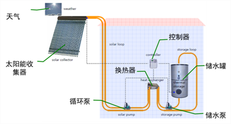
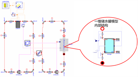
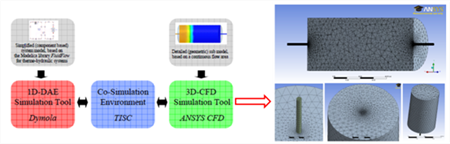
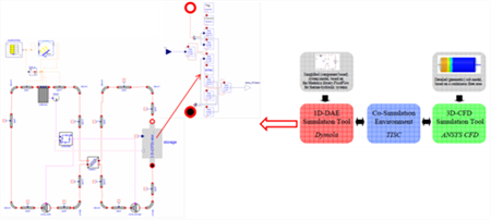
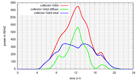
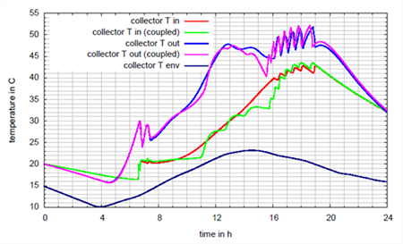
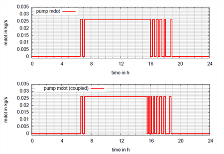
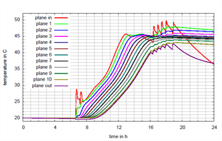
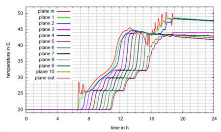
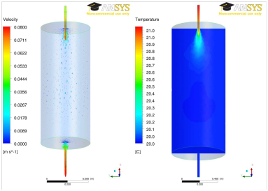
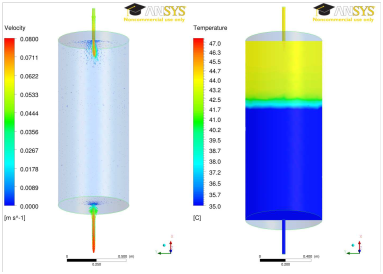
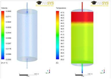
Background of the project Professor Manuel Ljubijankic of the University of Berlin and others, in conjunction with TLK Thermal Power Company (TISC), used the TISC simulation environment to realize the joint simulation of the three-dimensional thermal fluid model and analyzed the simulation results. Project proposals In order to better compare the simulation results, before building a three-dimensional fluid model, first use the Dymola software to build a solar water heater system model. The one-dimensional system model architecture is shown on the right: the length of the pipeline is set to exactly 1 m, and the water storage tank is divided into 10 horizontal temperature zones. The solar water heater system model was built based on Dymola hot fluid reservoir and ANSYS CFD software, and software co-simulation was carried out in TISC simulation environment. Three-dimensional storage tank model modeling requirements: • Reasonable discrete accuracy • The right computing speed • Appropriate interface position, the interface position is selected at the point where the flow state is stable, and the length of the water tank connection pipe is 0.275m A three-dimensional imitation Dymola model, in addition to the water tank model, the remaining system model reuse Implementation Effect Comparison of separate Dymola model simulation and TISC-based Dymola and Fluent joint simulation results • Calculate time comparison The software version for the one-dimensional Dymola model simulation is Dymola 7.4. The Dassl solver is used. The tolerance is 1e-4, and the temperature change of one day is calculated. The time is several tens of seconds. After coupling, a three-dimensional model, the calculation time is about twice the simulation time, the total time is about 50 hours, the computer is equipped with 8 cores, the main frequency is 2.8GHz, 32GM memory, and the operating system is Linux 11.2. In the joint imitation, the ANSYS CFD model uses 4-core parallel simulation, and the Dymola model uses single-core simulation with a synchronization time of 1 s. • Comparison of simulation results The total radiated power at noon exceeds 800 W/m^2. Both simulation methods are based on the power curve of the following figure: Graph of solar collector's heat absorption power, heat dissipation power and total power The overall trend of the resulting curves simulated by the two methods is consistent. The resulting curve changes more strongly after coupling the 3D model. The most important reason for this difference is that there is no momentum in the one-dimensional model and the spatial model is transformed into an overall size. Curves of the inlet, outlet and ambient temperature of solar collectors Similarly, the results of the one-dimensional model and the three-dimensional coupled model are roughly the same. The difference occurs after 16 pm, the solar radiation intensity drops significantly, and the controller behavior under the two simulation modes is significantly different. Pump flow curve caused by the switching characteristics of the controller The following two figures are the temperature curves of the inlet and outlet lines connecting the water storage tank, and the temperature curves of the 10 horizontal planes in the water storage tank. Observing the inlet temperature after sunset, an interesting phenomenon was found: the temperature of the one-dimensional model decreased significantly, while the inlet temperature of the three-dimensional model had only a small slope. The reason for this difference is that the 3D model contains natural convection. The heat loss of the connecting line is affected by the overall heat loss of the water storage tank. The heat convection generated by the upper layer of the water storage tank and the connecting pipe compensates for the heat loss of the pipeline. One-dimensional model simulation results One-dimensional coupled simulation results The figure below shows the flow field and temperature field of the vertical section of the water storage tank calculated by the CFD model at three times (6:44, 13:00, 24:00). Flow field and temperature field in water storage tank at 6:44 Flow field and temperature field in water storage tank at 13:00 Flow field and temperature field in water storage tank at 24:00 •to sum up ◆ Under the same boundary conditions, the simulation results of the two simulation methods are consistent. ◆In the morning and evening, the temperature is obviously affected by the flow switch characteristics. ◆ Three-dimensional water tank model shows more complex behavior ◆ If the stored thermal energy changes or the incoming mass flow switches between 0 and maximum flow, the 3D model exhibits an immediate response, which is due to the inclusion of momentum transfer and natural convection in CFD operations. Project value • A case study using a solar water heater illustrates a three-dimensional model joint simulation method • The comparison results of the two simulation methods are similar, which proves that the simulation method is feasible. • Detailed design of components can be carried out through 3D modeling of individual components and co-simulation of 1D models. The detailed 3D water storage tank model in this paper allows for more detailed problem analysis after fully considering the surrounding environment, such as optimizing the installation position of the temperature sensor or studying the natural convection phenomenon. • Fully discrete 3D water storage tank model requires computation time on modern computers to be approximately twice the simulation time Background of the project Professor Manuel Ljubijankic of the University of Berlin and others, in conjunction with TLK Thermal Power Company (TISC), used the TISC simulation environment to realize the joint simulation of the three-dimensional thermal fluid model and analyzed the simulation results. Project proposals In order to better compare the simulation results, before building a three-dimensional fluid model, first use the Dymola software to build a solar water heater system model. The one-dimensional system model architecture is shown on the right: the length of the pipeline is set to exactly 1 m, and the water storage tank is divided into 10 horizontal temperature zones. The solar water heater system model was built based on Dymola hot fluid reservoir and ANSYS CFD software, and software co-simulation was carried out in TISC simulation environment. Three-dimensional storage tank model modeling requirements: • Reasonable discrete accuracy • The right computing speed • Appropriate interface position, the interface position is selected at the point where the flow state is stable, and the length of the water tank connection pipe is 0.275m A three-dimensional imitation Dymola model, in addition to the water tank model, the remaining system model reuse Implementation Effect Comparison of separate Dymola model simulation and TISC-based Dymola and Fluent joint simulation results • Calculate time comparison The software version for the one-dimensional Dymola model simulation is Dymola 7.4. The Dassl solver is used. The tolerance is 1e-4, and the temperature change of one day is calculated. The time is several tens of seconds. After coupling, a three-dimensional model, the calculation time is about twice the simulation time, the total time is about 50 hours, the computer is equipped with 8 cores, the main frequency is 2.8GHz, 32GM memory, and the operating system is Linux 11.2. In the joint imitation, the ANSYS CFD model uses 4-core parallel simulation, and the Dymola model uses single-core simulation with a synchronization time of 1 s. • Comparison of simulation results The total radiated power at noon exceeds 800 W/m^2. Both simulation methods are based on the power curve of the following figure: Graph of solar collector's heat absorption power, heat dissipation power and total power The overall trend of the resulting curves simulated by the two methods is consistent. The resulting curve changes more strongly after coupling the 3D model. The most important reason for this difference is that there is no momentum in the one-dimensional model and the spatial model is transformed into an overall size. Curves of the inlet, outlet and ambient temperature of solar collectors Similarly, the results of the one-dimensional model and the three-dimensional coupled model are roughly the same. The difference occurs after 16 pm, the solar radiation intensity drops significantly, and the controller behavior under the two simulation modes is significantly different. Pump flow curve caused by the switching characteristics of the controller The following two figures are the temperature curves of the inlet and outlet lines connecting the water storage tank, and the temperature curves of the 10 horizontal planes in the water storage tank. Observing the inlet temperature after sunset, an interesting phenomenon was found: the temperature of the one-dimensional model decreased significantly, while the inlet temperature of the three-dimensional model had only a small slope. The reason for this difference is that the 3D model contains natural convection. The heat loss of the connecting line is affected by the overall heat loss of the water storage tank. The heat convection generated by the upper layer of the water storage tank and the connecting pipe compensates for the heat loss of the pipeline. One-dimensional model simulation results One-dimensional coupled simulation results The figure below shows the flow field and temperature field of the vertical section of the water storage tank calculated by the CFD model at three times (6:44, 13:00, 24:00). Flow field and temperature field in water storage tank at 6:44 Flow field and temperature field in water storage tank at 13:00 Flow field and temperature field in water storage tank at 24:00 •to sum up ◆ Under the same boundary conditions, the simulation results of the two simulation methods are consistent. ◆In the morning and evening, the temperature is obviously affected by the flow switch characteristics. ◆ Three-dimensional water tank model shows more complex behavior ◆ If the stored thermal energy changes or the incoming mass flow switches between 0 and maximum flow, the 3D model exhibits an immediate response, which is due to the inclusion of momentum transfer and natural convection in CFD operations. Project value • A case study using a solar water heater illustrates a three-dimensional model joint simulation method • The comparison results of the two simulation methods are similar, which proves that the simulation method is feasible. • Detailed design of components can be carried out through 3D modeling of individual components and co-simulation of 1D models. The detailed 3D water storage tank model in this paper allows for more detailed problem analysis after fully considering the surrounding environment, such as optimizing the installation position of the temperature sensor or studying the natural convection phenomenon. • Fully discrete 3D water storage tank model requires computation time on modern computers to be approximately twice the simulation time
Slicer and dicer(meat dicer) are used in different fields of food industrial such as for meat, cheese, vegetables, fruits etc. Helper`s slicer and dicer seies are applied in both restaurant and industrial plant. To produce portioned bacon, the Rib chopper will help. To make vegatable and meat mixture for dumpling production, QD02 vegetable dicer will be the best choice.
In addition to them,we also supply the cubing machines.
Potato Slicer,Food Chopper,Vegetable Dicer,Vegetable Cutter,Meat Dicer,Cubing Machines Helper Machinery Group Co., Ltd. , https://www.helperfoodmachiney.com